The Magnetic Field
Kreshnik Angoni and Kevin Lenton
Worksheet.docx
Worksheet.pdf
Additional Problems
Additional Problems2
Other Resources:
- Haliday & Resnick, Fundamentals of Physics 27.1-9
- Openstax
- Printable version
The Magnetic Force derives from the Electric Force in a different Frame of Reference
If you pour small iron particles around permanent magnets (either natural “lodestones” or manmade) an ordered pattern appears (fig.1). You can easily discern the presence of lines that become very dense at magnet extremes (poles). We say that a magnet builds a magnetic field in the space around it. This field is there all the time; its action (magnetic force) on iron particles makes it visible.
The definition of magnetic poles comes from these arbitrary definitions:
If suspended horizontally, the magnet pole that seeks the earth’s north is called the North pole (N); the other pole is the South Pole (S). The pole N of a magnet repels the pole N of another magnet and attracts its pole S. So, it turns out that the earth has its own magnetic poles and the S pole of the earth must be located at the geographic north pole!
It’s important to note that:
a) The location of poles for a permanent magnet “at its extremes” is somewhat un-precise.
b) If you break a magnet in the middle, each of the two pieces constitutes a new magnet with two poles N and S. That is to say magnets always come in dipoles: N and S together. The mythical magnetic monopole (N or S separately)has not been observed... yet. This fact means that the development of magnetic field theory is very different from that of electric fields.
Michael Faraday was a famous british scientist who first described magnetic fields and had the idea of defining magnetic “field lines”.
Description of the Magnetic Field Lines
a) The magnetic field vector B(x, y, z) characterizes the magnetic field at each point in space.
b) The magnetic field lines are closed loops. Outside the magnet, throughout all space, they go out of the north pole N and into the south pole S. Inside the magnet itself, they are aligned from pole S to pole N (see fig.2).
c) B(x, y, z) is always tangent to the field line passing through the point (x,y,z) and its magnitude(field strength) is proportional to the number of lines through a area perpendicular to the line direction at this point.

Imagine a plane P perpendicular to the “N–S” axis and midway between it (as shown in fig 2), the magnetic field lines cross this plane perpendicular to it. Depending on which side you observe, you will either see the field lines going into this plane or coming out. The convention is to draw a cross “x” to show a field line going into the plane (or into this screen, if you wish) and a dot “ • ” to show a field line going out of a plane (or out of this screen, if you wish).
Remember: We measure the electric field, i.e. vector E , at a point in space by measuring the electric force exerted on isolated charge of value +1C placed at this point ( Fel =+1* E ) . Unfortunately there is no isolated magnetic charge ( “magnetic charges” exist only as a dipole N – S ) so there is no equivalent for magnetic fields. You have to use indirect methods.
The Magnetic Force on a Moving Charge
However, the magnetic field is based on the “the magnetic force” whose existence is shown by experiment.
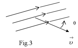
Experimental fact: The magnetic field only exerts a force on electric charge which is moving. Experiments show that when a particle with electrical charge “ q “ and moving with velocity v enters a magnetic field, a new type of force ” a magnetic force ” acts on it.
Measurements show that the magnitude of this force is
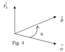
where is the angle measured from the direction of the velocity to the direction of the magnetic field lines. The magnetic force is equal to zero if the charged particle enters the magnetic field parallel or anti-parallel to the field lines and has a maximum force when it enters perpendicularly to them.
Just like for the electric field, the field strength is proportional to the field line density. The magnitude of the magnetic force is proportional to the density of magnetic field lines. As the density of field lines is proportional to B , we get that (2)
Finally, by selecting
(3)
one finds out that the magnitude of field vector is (4).
is directed perpendicularly to the plane defined by vectors and and its direction is that of the vector product . That is to say the direction is always perpendicular to this plane . So, simply put, it turns out that
- The direction of the magnetic field vector B is defined by the direction of the field poles (N to S).
- The direction of the magnetic force FB on a charged particle is defined by the rule of vector product (right hand or bottle cap rule) and the sign of charge ( q must be taken with its algebraic sign). It is always perpendicular to the velocity and the B field.
Note: The magnetic field does zero work on a charged particle because, at all times,
and the displacement is in the same direction as the velocity. So . This means that the magnetic force can never speed up or slow down a particle (change its kinetic energy), but it can change its direction.
Units of Magnetic Field B
The SI unit of magnetic field strength is “Tesla” (T). One definition is: a magnetic field of B = 1T exerts a force of 1N on an electric charge of +1C moving at 1m/s along a direction perpendicular to B . So, 1T =1N/(C*m/s) = 1N/(C/s)*m = 1N/A*m.
Another commonly used unit is the“gauss” .
IMPORTANT:
a) We are looking at the magnetic field by itself, without referring to the source of the field. From the beginning, the magnetic force is derived from the action of a field.
b) The definition of the magnetic field vector is related to electric charge. This is a first sign of a profound relationship between electric and magnetic phenomena.
MAGNETIC FORCE ON A CURRENT-CARRYING WIRE
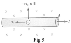
When there is a current in a wire, the electrons move in an ordered way with a drift velocity . If this wire is placed inside a magnetic field, the magnetic force they experience is transmitted to the wire. If there is no current, the electrons move irregularly and the net force exerted on the wire becomes zero. Let’s calculate the magnetic force on a wire with section “A” and length “l” carrying the current “I” when it is placed perpendicularly (Fig.5) to a uniform magnetic field B . The magnetic force acting on each electron is
(6) e-BD
If n is the electron density, there are n *A*l electrons inside a length l of wire. As each of them experiences the same force (6), the net magnetic force they transmit to the wire is
where is the unit vector perpendicular to both and and is the current magnitude and is a vector with magnitude “l” and same direction as the current (positive charges = opposite to the electrons)
in the wire.
Remember that the magnetic force on a wire that carries current is always perpendicular both to wire and to the magnetic field B.
Remember that the magnitude of this force does depend on the angle between them, as well.
EFFECT OF MAGNETIC FIELD ON A CURRENT-CARRYING LOOP
What happens when a current-carrying loop is placed inside a uniform magnetic field?
The direction of the magnetic force on each edge of the loop will be different because the direction of the current in each side is different, but same magnitude of course.
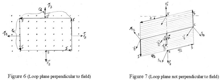
Let’s consider closely the case of a plane rectangular loop with sides a and c which carries a current I and is placed inside a uniform magnetic field with strength B (see Figure 6).
When the loop (more technically the plane of the loop) is perpendicular to B (B is coming out of the screen in Fig.6), the directions of the magnetic forces on each wire section are such that they pull out on each section – they tend to stretch out the loop!
However, if the loop is turned by an angle about the central axis (points S, S’ in Fig.7), the forces exerted on the upper and lower sections still pull out. But, the forces exerted on the side sections now have components which act to rotate the loop. In other words the magnetic force now creates a net torque on the loop. The net force is still zero.
The magnitude of each side force is
The perpendicular component (the component which rotates)is (see Fig. 8) :
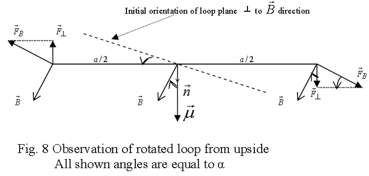
As its lever arm is a/2 , the related torque on the loop is
(8)
The rotational action of the two side forces produces the net torque about the central axis SS’ with magnitude
(9)
Where A is the loop area
We derived the expression (9) for the case of a single turn rectangular plane loop. Similar calculations show that the same expression is valid for any shape of a plane loop. If a loop of N tightly fixed turns is placed inside an uniform magnetic field, the net torque exerted on the loop has the magnitude (10)
Magnetic Moment: A more compact way to express the torque on current carrying loops
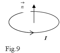
First, one defines the loop unit vector normal to the loop surface respecting the right hand rule (fig. 9).
Next, one defines the magnetic dipole moment of a plane loop (of any shape) constituted by N turns with area A as
(11)
Note that the direction of this vector is normal to the plane of the loop, and obeys the right hand curl rule: curl your right hand fingers in the direction of the current and the thumb gives the direction of the normal.
Then, one expresses the net torque on the current-carrying loop by a cross product
(12)
Note that when is in the same direction as the torque is zero. If then the torque is maximum. This means the torque wants to turn the loop such that the B field vector and the magnetic moment vector are aligned.