Capacitors
Kreshnik Angoni and Kevin Lenton
Word Worksheet
PDF Worksheet
Additional Problems
Other Resources:
- Haliday & Resnick, Fundamentals of Physics 21.1-5
- Openstax
- Printable version
Learning Objectives
After reading this page, watching the videos and reviewing the exercises, you will be able to:
- understand the relation between charge and voltage in a pair of parallel conducting plates.
- define capacitance.
- define and calculate equivalent capacitance for series and parallel connections.
- understand the mechanism and calculate the amount of energy storage in a capacitor.
Capacitors are an extremely common electrical component, because they can store charge and energy. In addition they charge and discharge over time intervals determined by their value and therefore they are essential for any timing circuit (see AC circuits).
Introduction to Capacitors
As explained previously, the presence of electric charges in a space creates an electric field.
If another charged particle (for instance an electron e-, or a proton p+ or an ion) appears somewhere in this space, the electric field will exert a force on it and when this particle moves inside the electric field, the electric force or its “source”, i.e. the electric field, does work. This means that the electric field possesses energy and it can be thought of as an “energy container” or “energy source”.
In principle, you can “store energy” in space by using any possible configuration of electric charges. One common configuration, called a capacitor, corresponds to two charged conductors (presented as parallel plates ┤├) that are separated by an insulator. The most common insulator in our examples will be air. The plates may be in a plane, cylindrical or spherical.
Consider that the battery B (shown in fig.1) is a “box” that keeps constant the difference of potential V1 between its terminals, no matter what circuit is connected to them. Once the plates of capacitor C are connected (by metallic wires) to the battery terminals, they start getting charge from the terminal and this builds the difference in potential V between the capacitor plates. The electromotor force “emf”
of battery removes some free electrons from one plate of capacitor , and in this way charges it positively “ +” and transfers the same amount of electrons to the other plate of the capacitor (charging it negatively “-“ ). At the end of transfer, each plate gains the same magnitude of charge, but of different signs (+Q,-Q). For a perfect capacitor, these charges are distributed uniformly on the surface of the conducting plates. As the area of both plates is equal, the same magnitude of charge density (but opposite sign) is present on each of them. It turns out that, for a given potential difference between them, the plates of capacitor can only hold a limited amount of charge “Q”.
Once this amount Q is stored on the plates, the battery is not able to remove any more charges from the plates of capacitor and the charge transfer is stopped.
Assume that, after this, that someone disconnects the battery. The charges will remain on plates due to the mutual attraction with the other sign charge on the other side (Fig.2) and also because the charges have nowhere to go!
So, the capacitor keeps the charges +Q, -Q and the difference of potential V between its plates.

Capacitance: The Relationship between the Charge Q and the Potential V
The strength of the electric field E close to the surface of a conductor is proportional to the charge density () on its surface. As, for a given area and uniform distribution
, we get () where Q is the total charge on surface.
The difference of potential ∆V between two locations inside a field is proportional to the field strength (). Therefore the () between the two capacitor plates (the two locations in the field) is proportional to the charge Q on each of them. Then if we take the potential on the negative plate V(-) = 0, then V(+) known as the electric potential of the capacitor is proportional to Q and vice-versa. So
Or
where C is a constant of proportionality and is called the capacitance of the capacitor. Note that C is constant for any particular capacitor. Its unit in the SI system is the Farad (1F); 1F = 1Coulomb/Volt
For a given difference of potential V between the terminals, the greater the capacitance C, the greater the quantity of stored charge Q and also the greater the amount of electric energy stored inside the capacitor.
The capacitance is the main parameter of a capacitor. It measures its efficiency in storing energy. For general purpose capacitors, the capacitance values are in pF(picofarad), nF(nanofarad), (microfarad).
The Capacitance only depends on the Capacitor Dimensions, The E Field only depends on the Charge Density
Fig.2 presents the electric field in the empty space between two plates of a capacitor. If the plate separation d is small, you may ignore the edges and consider only the field in central region. The more you ignore edge effects, the more ideal the capacitor becomes. In this region you may use the model of the field from a charge Q distributed uniformly on a large surface.
We have
found that this field is uniform, directed vertically to the surface and its magnitude is
Since there are two plates with the same charge density producing fields with the same magnitude and direction (from the “+” to the “-“ plate), It turns out that, for an area plate “A” the magnitude of net electric field in a capacitor is
This field is uniform; so the potential difference between the two plates is
Then
And
The expression (6) shows that, in a vacuum, the capacitance of a given capacitor depends only on its geometry and dimensions. If the capacitor shape is not plate, the expression for its capacitance is more complex than (6) but in all cases it depends only on its dimensions.
CAPACITORS IN SERIES AND PARALLEL
For certain situations you may want to combine capacitors, either because you have a limited selection of capacitors, or there are other constraints e.g. exceeding the breakdown voltage, when a spark goes from one plate to the other. There are two main ways to connect several capacitors; in series and in parallel.
Capacitors in Series
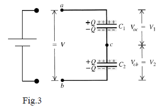
Figure 3 presents the scheme of two capacitors connected in series. Consider if you connect the points a and b to
the battery terminals for some time; then disconnect them.

During the contact with the battery, the capacitors C1 and C2 acquire the same charge amount Q on their plates because the exterior charges +/- Q shifted by battery induce the same magnitude of charge -/+Q to the interconnected plates.
Tip 1: Capacitors in series always carry same charge on each plate.
Using this tip, and knowing the value of capacitances C1 and C2, you may calculate the potential difference across each capacitor, V1 and V2 respectively, as follows:
Then
This expression shows that two capacitors connected in series function the same way as an equivalent capacitor with capacitance Ceq such that
In the general case of N capacitors connected in series, the equivalent capacitance is
Note that, for the same charge amount “Q” stored on the plates, this “equivalent capacitor” supports higher voltage on its terminals” V=V1+V2+V3+…”.
On the other hand, the capacitance of the combined capacitors is always less than the value of the capacitors themselves. One way of looking at it is that the voltage across each capacitor is always less than the total voltage and therefore the charge each capacitor carries is less than if that capacitor was attached directly to the battery.
Capacitors in Parallel

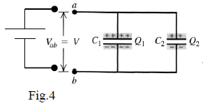
Figure 4 presents the scheme of two capacitors connected in parallel. In this case, the same potential difference is applied to the two capacitors and the battery emf has moved the total charge amount Q1 + Q2. The charges Q1 and Q2 depend on the capacitance of capacitors as follows
and
So, the equivalent capacitor would get the total charge
and its capacitance would be
In the most general case of connecting N capacitors in parallel, the equivalent capacitance is equal to
The “equivalent capacitor” offers higher storage capacity of charge ”Q1+Q2+..” for the same voltage.
Another way of looking at it is that the area on which charge can be stored is increased, therefore the charge storage must increase as well.
ENERGY STORED IN A CAPACITOR
The stored energy in a capacitor comes from the work done in accumulating the charges onto the plates. Importantly, another way of looking at the stored energy is that is contained in the electric field created in the space between the plates by the charge on the plates. This stored energy is due to the work done by the emf of the battery as it moves “free electrons” from one plate (that becomes charged “+”) to the other plate (that becomes charged “-”). Note that the electron path passes through the wires and battery and not through the space between the plates.
Let’s consider a circuit containing only a battery connected to a capacitor at an intermediary point in time when the plate’s charge is q (not the final charge Q) and the potential difference between them is v (not the final volage V). The work dW done by the battery, for the transport of the next elemental charge “-dq” from the “+” plate to the “-“ plate is external work done on the system electric field- charge. That is to say the battery loses work and the electric field (arising from the charge arrangement), gains work.
The work done will be equal to the potential difference times the charge transferred, as shown here:
As then from (15)
The total work for the battery to move the charge is:
You can rewrite this expression, if you assume the initial potential was zero, then:
Which is the formula most quoted.
The principle of energy conservation tells that this external work goes towards increasing the potential energy stored inside the capacitor.
Real Capacitors and Dielectrics
Capacitors come in all sorts of different shapes and sizes. The capacitors you often use look small, but in reality contain large sheets of conductor folded neatly into these small packages.
Most real capacitors contain an insulating material between the plates. This material is called a dielectric (insulator) material.
The dielectric is very practical for several reasons:
a) It stops the plates from shorting out;
b) It increases the maximum potential difference supported by the capacitor, by reducing the electric field between the plates;
c) It increases the capacitance of the capacitor compared to the capacitor without dielectric;
These factors make your capacitor with dielectric more efficient: your capacitor can store more charge, for a given potential.
Examples
How to combine multiple capacitors in parallel and in series
What happens when you charge two capacitors and then connect them together?