Sources of Magnetic Field
Kreshnik Angoni and Kevin Lenton
Worksheet.docx
Worksheet.pdf
Additional Problems
Other Resources:
- Haliday & Resnick, Fundamentals of Physics 29.1-4
- Openstax
- Printable version
We saw the way a magnetic field acts on charged particles in movement and on a current-currying wire or loop . But, we have not explained the origins of the magnetic field itself, yet. It’s important to remember that we cannot have a unique magnetic pole and the quantitative definition of a magnetic field makes use of “an electric charge in movement”. The first experiments were published by Oersted. Also, he was the first to prove experimentally that a carrying current wire exerts a force on another carrying current wire as if it were a magnet itself.
CURRENTS PRODUCE MAGNETIC FIELD: A LONG, STRAIGHT WIRE
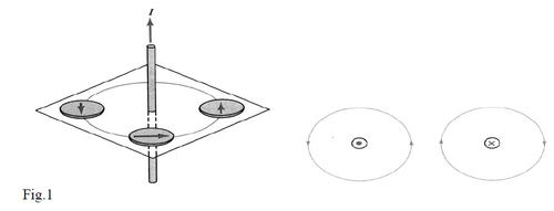
You may verify easily, by use of iron particles, that a straight long wire carrying current creates a magnetic field with circular field lines around it. Also, by using a compass needle (fig.1), one may find that the field direction obeys the right hand curl rule (or bottle-cap rule): If the thumb is in the direction of the current , the curled fingers of the right hand indicate the direction of the magnetic field (see Fig.1 and the video below). The magnitude of the field vector is constant around a circle centered at wire and it depends only on the current in the wire I and the distance from it R. It can be shown that the magnetic field is given by the expression
(1)
where the constant is known as the permeability constant of free space. (free space =vacuum)
Note: As the magnitude of the field decreases with distance it turns out that the density of field lines decreases with increase of distance, too.

MAGNETIC FORCE BETWEEN TWO PARALLEL WIRES
Wires carrying current produce magnetic fields, but those magnetic fields can apply force on other current carrying wires.
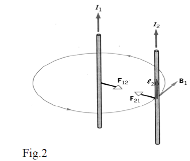
Consider two long straight wires carrying the currents and at a distance d from each other. The first wire creates a magnetic field with magnitude at distance d ; it is perpendicular to the direction of current passing thought the second wire. Referring to a length on the second wire, you can show that the magnitude of the magnetic force exerted on this length is
(2)
When considering the magnetic force exerted on the first wire by the magnetic field of the current in the second wire, you get
(3)
Note that, if the currents have the same direction (fig. 2) the exerted forces are attractive and if the currents have opposite directions the exerted forces are repulsive.

By comparing the expressions (2) and (3) you can see that the same force magnitude is exerted on the unit length of each wire
(4)
It is very interesting to mention that the definition of the current unit (the Ampere) is based precisely on this expression: The current through two parallel wires at a distance 1m is 1A when the magnitude of the magnetic force exerted on 1m length of each of them is equal to N.
Examples
BIOT-SAVART LAW FOR A CURRENT ELEMENT
The definition of magnetic field due to current in a long straight wire opened the way for finding a basic expression in calculation of magnetic fields created by different forms of wires (not only straight). As we know from the similar situations in case of electric field calculations, at first, one starts by the definition of field due to an infinitesimal element and then you follow up with an integral calculation.
To make our lives easier we can define
to expression (1) and get it in form
(5)
Which, you will note, is a similar expression to that of the magnitude of the electric field from an electric charge uniformly distributed along a long straight wire (6)
Without going into detailed explanations, we note that the symmetry between the magnetic and electric fields expressions is much more profound than it first appears. The electric and magnetic forces must fundamentally be the same!
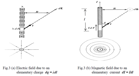
As a second step, note that the elementary field vector from an elementary charge dq = λdl is given by the expression
(7)
is the unit vector directed from the charge “dq” to the point where the electric field is calculated. Then, by using integration along the wire you get equation(6) for the magnitude of the field.
Following the same method, you can derive equation (5) for the magnitude of the magnetic field as the integral of the elementary magnetic fields vectors due to elementary currents dI = Idl in the wire. When comparing the expressions (6) and (7) one observes that the distance appears as in expression (6) and at expression (7).
So, due to symmetries between (5) and (6), one should expect a factor “ “ for the elementary magnetic field expression as well. Also, similarly to “dq” in (7) you might expect proportionality to “ dI ”.
Besides these similarities, you should remember that the directions of the E and B fields depend on different rules; (see fig.3.a) but obeys the vector product rule (see fig.3.b).

Using these ideas you can get the general expression:
(8)
In this expression, is the infinitesimal length vector whose direction is defined by the current and is the unit vector directed from the elementary current to the point where the magnetic field is calculated.
Equation (8) is known as the Bio-Savart law for the magnetic field due to an elementary current dI.
From equation (8), you can see that the magnitude of the elementary magnetic field is
(9)
Where is the angle between the direction and direction at the infinitesimal length location.
Important note: The elementary current only exists in the physics world where it is very helpful for calculations. There is no way to isolate or measure an elementary current in the laboratory.
Calculating the magnetic field from a finite length wire carrying a current I

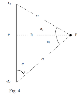
The set-up is shown in Figure 4. A short length of wire (Length=L1+L2) is carrying a current I. All the infinitesimal contributions of dB, at the point in question point P, are directed perpendicularly into the page at P, as determined by the right hand rule. The net magnetic field is the sum of all these contributions and therefore will also be directed into the page. To solve the problem you can divide up the wire into upper and lower parts. The division is defined by the perpendicular distance R. Using this artificial division, the net magnetic field at point P from the wire (fig.4) is constituted by two contributions; one due to the part of the wire below R and one due to the part above R.
We will calculate each of these contributions and sum them up.That is to say, integrate them!
So, let’s start by calculating the contribution from the lower half (see fig.3(b). The magnitude of dB (contribution of current element at distance “” from the level of considered point) is
(8)
From the figure 3.b you can see that and
So:
(10)
Then, the contribution from the lower part of wire with length L1 is
(11)
which means a magnitude equal to
(12)
You can get the direction from the right hand rule.
Similarly, the contribution to the field from all elements in the upper part of wire is:
(13)
Finally, the net magnitude of magnetic field due to a finite length wire () is given by the expression
(14)
Magnetic Field from an Infinitely Long Wire
Note that, for an infinite long wire, and the expression (14) gives
Which is the same expression as equation (1).