Electromotive Force and Kirchoff's Rules
Kreshnik Angoni and Kevin Lenton
Worksheet.docx
Worksheet.pdf
Additional Problems
Other Resources:
- Haliday & Resnick, Fundamentals of Physics 27.1-9
- Openstax
- Printable version
ELECTROMOTIVE FORCE
The terminal of a charged battery contains stored electric charges that build an electric field in
the space around it. Once we fix the end of a conducting it wire to (+) terminal, this electric field
attracts the free electrons from the wire into the battery and a current is produced inside the wire. But
this is an instantaneous current because the wire gets quickly the potential of terminal and the charge
movement stops. If we fix the other end of wire to the (-) negative terminal, we close the circuit and after this the
current through the wire becomes steady. The steady current is due to the fact that there is a constant
potential difference between the two wire ends, all the time.
Consider an electric circuit (Fig. 1) where the current I is steady and flows only in one direction;
we call this a DC current. The positive charges leave the higher potential (terminal +) and move
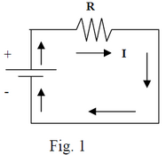
through the resistor R toward the lower potential(terminal -). Once inside the battery, the positive charges have to move from the lower to the higher potential so that the dc current in the circuit be steady. Note that the electrostatic field inside the battery has opposite direction to their motion and its action would block the current. We say that the positive charges overcome an electrostatic potential barrier (hill) inside the battery. How does this happen? There is only one answer; the necessary energy is provided by external (non-electrostatic) sources of energy and for a general purpose battery the external source is a source of chemical energy.
How a Battery Works
Actually, this energy is related to a set of chemical reactions that happen inside a battery. In a lead–
acid cell, a PbO2 plate and a Pb plate are immersed into an aqueous solution of H2SO4. One part of
H2SO4 molecules dissociate under the action of water molecules into positive ions (H+) and negative
ions (SO4-). Due to respective chemical affinity the following reactions happen at interface of plates:
At the PbO2 plate: .
2 electrons removed from the PbO2 plate; it becomes Terminal +
At the Pb plate: .
2 electrons stored at the Pb plate; it becomes Terminal -
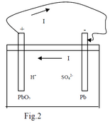
So, the first reaction “stores q= +2e” on plate “+”while the second
reaction “removes q = +2e” from plate “-“. Then, those charged plates
build (inside the battery) an electric field that pushes ions away from the
“chemically affine plate”. In an open circuit situation, the chemical
reactions at plates stop when the charge of plates gets such that the
related electric field blocks further movement of ions versus plates.
For a lead battery, this situation corresponds to the potential difference 2.05V between the two plates
in open circuit. When the battery is switched into a closed circuit, the positive charges go via the
circuit into the terminal “-“ ( or negative charges into terminal “+”). This decreases the net charge of each
terminal and the related internal electric field. As consequence, inside the battery, other ions move
toward the plates and the rate of chemical reactions increases instantaneously. The moving ions
transport “+” charges toward “+” plate and “-“ charges toward “-“ plate. This is equivalent with the
current (direction of + charges) from the lower potential to the higher potential inside the battery (Fig.2).
A dynamic equilibrium between the field and chemical reactions rate is built inside the battery due to
the principle of charge conservation condition: The magnitude of current must be the same outside in
circuit) and inside the battery. This way, the number of e- leaving Pb plate versus circuit each second
is equal to the number of e- stored into it chemically.
+
-
I
R through the resistor R toward the lower potential(terminal -). Once inside
the battery, the positive charges have to move from the lower to the higher
potential so that the dc current in the circuit be steady.
Note that the electrostatic field inside the battery has opposite direction to
their motion and its action would block the current. We say that the positive
charges overcome an electrostatic potential barrier (hill) inside the battery.
How does this happen? There is only one answer; the necessary energy is
provided by external (non-electrostatic) sources of energy and for a general
purpose battery the external source is a source of chemical energy.
The chemical reactions decrease the ions concentrations around plates and produce a
variation of ions’ concentration in the solution. The diffusion processes which tent to uniform the
concentrations bring other ions close to plates moving them “uphill the potential” and so on.
Simply put, from current modelling point of view, the chemical source provides an external work
which moves the positive charges uphill the electric potential inside the battery.
The work provided by a non-electrostatic source to move the charge +1C from the lower potential to
the higher potential terminal is known as emf1 and presented by the symbol Ɛ.
When moving the charge q uphill the potential difference, the emf source achieves the work
(3)
Definition of EMF
Like potential difference, the emf is defined as the work done during the displacement of +1C
charge but one must not forget their different physical origin. The source of potential difference
is the electrostatic field while the source of emf is a non-electric phenomenon.
In an electric circuit, there is one emf, at least. It provides the charge distribution at the origin of the
electrostatic field which drives the current. Note that the source of emf is not always chemical. It may
be magnetic (electric generator), mechanical (Van de Graff generator), etc..
When a charged battery is part of an open circuit, there is a potential difference
between its terminals. In this case, if a charge +q is moved from “-“ plate to “+” plate, the non-electric
source emf provides the amount of work which goes to increase the
electrostatic energy of battery by
(4)
In a closed circuit like that in Fig. 1, the potential V applied between the ends of the resistor R is
expressed (Ohms’law) as and it is equal to that on battery terminals . So, considering an
ideal source (without internal resistance), one would find
(5)
Equation (5) tells that, in a closed circuit containing an ideal source emf and a resistor, the potential
rise (Ɛ ) inside due to emf source is equal to potential drop (I*R ) through the resistor in the circuit.
A real battery in a closed circuit gets heated. This shows that it has a resistance-like behaviour, or in
other words it presents an internal resistance to the current. So, it comes out that a real source in a
circuit is equivalent to an ideal source plus a resistance (r) in series (Fig.3). In this case, one
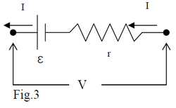
part of work Wext provided by emf goes to compensate for
potential drop through the resistance I*r and the remaining part
to pull “+” charges uphill the potential barrier inside the battery.
(6)
So, the terminal potential difference (Vclosed) of a battery in a closed circuit is smaller than its emf Ɛ.
Equation (4) shows that one may measure Ɛ by Vopen measurements. For a real battery in a circuit
with a resistance R, the equation (5) transforms to
(7)
and
(8)
1 “Electromotive force”. This wrong nomination (because Ɛ is energy and not force) remained for historical purposes.
2 In an electrical circuit, one uses the notation Vab = Va - Vb , where Va > Vb
KIRCHHOFF RULES
There are two circuit-analysis laws that are so simple that you may consider them “statements of the obvious” and yet so powerful as to facilitate the analysis of circuits of great complexity. The laws are known as Kirchhoff’s Laws. The first one, known both as “Kirchhoff’s Voltage Law” and “The Loop Rule” states that, starting on a conductor , if you drag the tip of your finger around any loop in the circuit back to the original conductor, the sum of the voltage changes experienced by your fingertip will be zero. (To avoid electrocution, please think of the finger dragging in an actual circuit as a thought experiment.)
Kirchhoff’s Voltage Law (a.k.a. the Loop Rule)
To convey the idea behind Kirchhoff’s Voltage Law, I provide an analogy. Imagine that you are exploring a six-story mansion that has 20 staircases. Suppose that you start out on the first floor. As you wander around the mansion, you sometimes go up stairs and sometimes go down stairs. Each time you go up stairs, you experience a positive change in your elevation. Each time you go down stairs, you experience a negative change in your elevation. No matter how convoluted the path of your explorations might be, if you again find yourself on the first floor of the mansion, you can rest assured that the algebraic sum of all your elevation changes is zero.
To relate the analogy to a circuit, it is best to view the circuit as a bunch of conductors connected by circuit elements (rather than the other way around as we usually view a circuit). Each conductor in the circuit is at a different value of electric potential (just as each floor in the mansion is at a different value of elevation). You start with your fingertip on a particular conductor in the circuit, analogous to starting on a particular floor of the mansion. The conductor is at a particular potential. You probably don’t know the value of that potential any more than you know the elevation that the first floor of the mansion is above sea level. You don’t need that information. Now, as you drag your finger around the loop, as long as you stay on the same conductor, your fingertip will stay at the same potential. But, as you drag your fingertip from that conductor, through a circuit element, to the next conductor on your path, the potential of your fingertip will change by an amount equal to the voltage across the circuit element (the potential difference between the two conductors). This is analogous to climbing or descending a flight of stairs and experiencing a change in elevation equal to the elevation difference between the two floors.
If you drag your fingertip around the circuit in a loop, back to the original conductor, your finger is again at the potential of that conductor. As such, the sum of the changes in electric potential experienced by your finger on its traversal of the loop must be zero. This is analogous to stating that if you start on one floor of the mansion, and, after wandering through the mansion, up and down staircases, you end up on the same floor of the mansion, your total elevation change is zero. This is another way of applying the conservation of energy: The change in gravitational potential energy is zero, if there is no change in vertical height.
In dragging your finger around a closed loop of a circuit (in any direction you want, regardless of the current direction) and adding each of the voltage changes to a running total, the critical issue is the algebraic sign of each voltage change. In the following example we show the steps that you need to take to get those signs right, and to prove to the reader of your solution that they are correct.
Example
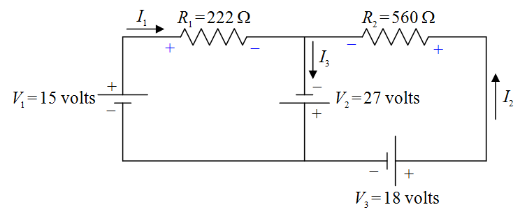
Find the current through each of the resistors in the following circuit.
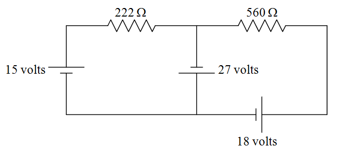
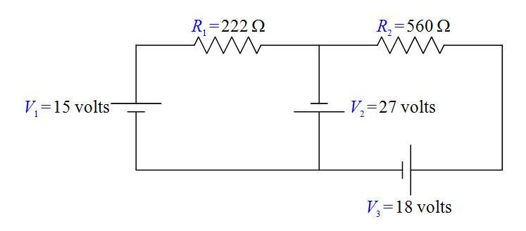
Before we get started, let’s define some names for the given quantities:
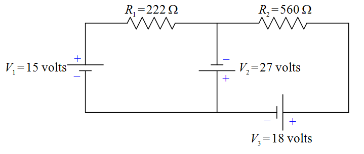
Each two-terminal circuit element has one terminal that is at a higher potential than the other terminal. The next thing we want to do is to label each higher potential terminal with a “+” and each lower-potential terminal with a “-”. We start with the seats of EMF. They are trivial. By definition, the longer parallel line segment, in the symbol used to depict a seat of EMF, is at the higher potential.
Next we define a current variable for each “leg” of the circuit. A “leg” of the circuit extends from a point in the circuit where three or more wires are joined (called a junction) to the next junction. All the circuit elements in any one leg of the circuit are in series with each other, so, they all have the same current through them.
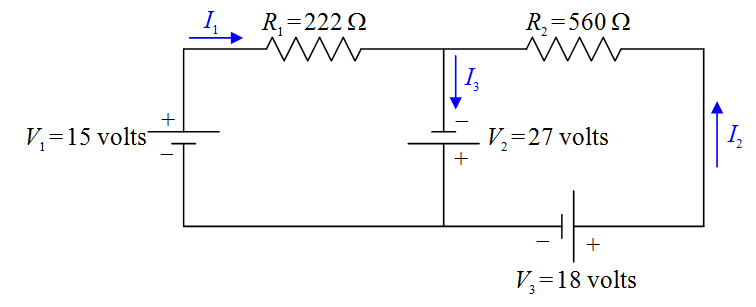
Note: In defining your current variables, the direction in which you draw the arrow in a particular leg of the circuit, is just a guess. Don’t spend a lot of time on your guess. It doesn’t matter. If the current is actually in the direction opposite that in which your arrow points, you will simply get a negative value for the current variable. The reader of your solution is responsible for looking at your diagram to see how you have defined the current direction and for interpreting the algebraic sign of the current value accordingly.
Now, by definition, the current is the direction in which positive charge carriers are flowing. The charge carriers lose electric potential energy when they go through a resistor, so, they go from a higher-potential conductor, to a lower-potential conductor when they go through a resistor. That means that the end of the resistor at which the current enters the resistor is the higher potential terminal (+), and, the end at which the current exits the resistor is the lower-potential terminal (-) of the resistor.
Now let’s define some variable names for the resistor voltages:
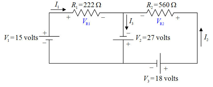
Note that the + and – signs on the resistors are important parts of our definitions of and . If, for instance, we calculate to have a positive value, then, that means that the left (as we view it) end of is at a higher potential than the right end (as indicated in our diagram). If turns out to be negative, that means that the left end of R1 is actually at a lower potential than the right end. We do not have to do any more work if turns out to be negative. It is incumbent upon the reader of our solution to look at our circuit diagram to see what the algebraic sign of our value for means.
With all the circuit-element terminals labeled “+” for “higher potential” or “–” for “lower potential,” we are now ready to apply the Loop Rule. I’m going to draw two loops with arrowheads. The loop that one draws is not supposed to be a vague indicator of direction but a specific statement that says, “Start at this point in the circuit. Go around this loop in this direction, and, end at this point in the circuit.” Also, the starting point and the ending point should be the same. In particular, they must be on the same conductor. (Never start the loop on a circuit element.) In the following diagram are the two loops, one labeled (1) and the other labeled (2) .
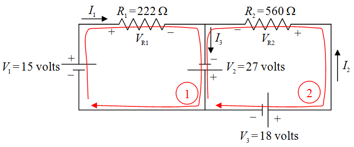
Now we write KVL (1) to tell the reader that we are applying the Loop Rule (Kirchhoff’s Voltage Law) using loop (1) , and transcribe the loop equation from the circuit diagram:
KVL (1)
The equation is obtained by dragging your fingertip around the exact loop indicated and recording the voltage changes experienced by your fingertip, and then, remembering to write “= 0.” Starting at the point on the circuit closest to the tail of the loop 1 arrow, as we drag our finger around the loop, we first traverse the seat of EMF, . In traversing we go from lower potential (-) to higher potential (+). That means that the finger experiences a positive change in potential, hence, enters the equation with a positive sign. Next we come to resistor R1. In traversing R1 we go from higher potential (+) to lower potential (-). That’s a negative change in potential. Hence, VR1 enters our loop equation with a negative sign. As we continue our way about the loop we come to the seat of EMF and go from lower potential (-) to higher potential (+) as we traverse it. Thus, enters the loop equation with a positive sign. Finally, we arrive back at the starting point. That means that it is time to write “ = 0.”
We transcribe the second loop equation in the same fashion:
KVL (2)
With these two equations in hand, and knowing that and , the solution to the example problem is straightforward. (We leave it as an exercise for the reader.) It is now time to move on to Kirchhoff’s other law.
Kirchhoff’s Current Law (a.k.a. the Junction Rule)
Kirchhoff’s junction rule is a simple statement of the fact that charge does not pile up at a junction. (Recall that a junction is a point in a circuit where three or more wires are joined together.) I’m going to state it two ways and ask you to pick the one you prefer and use that one. One way of stating it is to say that the net current into a junction is zero. Check out the circuit from the example problem:
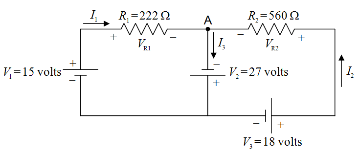
In this copy of the diagram of that circuit, I put a dot at the junction at which I wish to apply Kirchhoff’s Current Law, and, I labeled that junction “A.”
Note that there are three legs of the circuit attached to junction A. In one of them, current I1 flows toward the junction. In another, current I2 flows toward the junction. In the third leg, current I3 flows away from the junction. A current away from the junction counts as the negative of that value of current, toward the junction. So, applying Kirchhoff’s Current Law in the form, “The net current into any junction is zero,” to junction A yields:
Kirchoff Current Law applied to point A
Note the negative sign in front of I3. A current of – I3 into junction A is the same thing as a current of I3 out of that junction, which is exactly what we have.
The other way of stating Kirchhoff’s Current Law is, “The current into a junction is equal to the current out of that junction.” In this form, in applying Kirchhoff’s Current Law to junction A in the circuit above, one would write:
Kirchoff Current Law applied to point A
Obviously, the two results are the same.
These two laws give you a set of equations that you can use to solve for unknowns.
COMBINATIONS OF RESISTORS
A common question is to find “the equivalent resistor to a set of resistors into a circuit”. To find the equivalent resistor group them into sets of resistors in series and resistors in parallel.
Resistors in Series
When two resistors are connected to
the battery, the terminal difference of
potential (V) applies to the end points
(1,4) and the same current passes
through each resistor. Ohm’s law tells
that, following the current sense, the
potential drops by I*R1 between points
(1-2), remains constant in wire section
(2-3), drops by I*R2 in section (3-4).
As the total potential drop (-V) between points (1-4) is the sum of two subsequent potential drops:
(9)
So,
.
For N resistors in series one gets
Remember that if is largest resistance in the set, .
Resistors in Parallel
Fig.9
In this case one applies the first Kirchhoff’s rule :
(11)
Next, one expresses the current at each resistor through the potential drop at its ends (the same V)
By substituting at (11) one gets
(13)
For a set of N resistors in parallel one gets the equivalent resistor value as
(14)
Remember that if Rsmall is smallest resistance of the set, Req < Rsmall.
DIRECT CURRENT INSTRUMENTS
Current Measurement: The Ammeter
The Ammeter is a device that measures the current passing by a given point of circuit. This
instrument has a very low resistance. One can measure the current by introducing the ammeter in
series with the circuit (Fig.10) at the point of interest. As its resistance is very low, its introduction in
circuit does not alter significantly the current in circuit. The found value of current is practically the
same as in the closed circuit without ammeter.
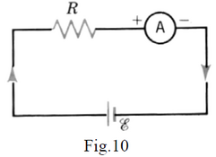
Take Home Message: Ammeters have very low resistance. They must be put in series with the circuit because they do not affect the current. If they were put in parallel they would short out the circuit.
Voltage Measurement: The Voltmeter
The voltmeter is used to measure the potential difference between two points in a circuit. This
instrument has a very large resistance. You can measure the difference of potential between two points
by connecting the voltmeter in parallel to the circuit between these two points (Fig.11).
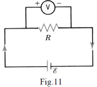
As the resistance of voltmeter is large, its introduction does not affect
significantly the current in circuit. Thus, the potential drop to the resistor R
(V=I*R) is essentially the same as if the voltmeter were not in circuit.
Take Home Message: Voltmeters have a very high resistance, so practically no current flows through them. They must be put in parallel with the circuit.
Example
For an ideal source Ɛ =12V and R = 20Ω in circuit I = 12/20 = 0.6A. When using a voltmeter with R=10KΩ, 1/Req = (1/20) + (1/104) = 0.0501 Req = 1/0.0501 = 19.96Ω and I1=12/19.96 = 0.601A. As the current passing through voltmeter is 12/10000 = 0.012A, it turns out that the current through the resistance R is practically unchanged (0.601-0.012~0.6A).
RC CIRCUITS
RC circuits are so named because they have a resistor and and a capacitor in series.
When a capacitor is connected to a battery in a circuit, the electric charge will be stored into its plates
until it gets to a certain maximum value . During this time a current will pass through the circuit and
a potential difference exist between capacitor plates.
Once the capacitor gets the charge
no more current pass through the circuit; the potential difference between its plates becomes equal
to ε and .
Let’s see what way happens this process in the case of a circuit that contains an
emf source ε, a resistor R and a capacitor C (fig.14).
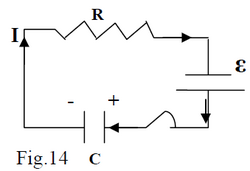
In the following proofs for discharging and charging a capacitor in an RC circuit, the quantities that change with time are noted by lowercase letters and the ones that do not change with time are noted by uppercase letters.
CHARGING A CAPACITOR
By using the 2nd Kirchoff’s rule we get (21)
where is the potential drop through the capacitor and
is the potential drop through the resistor.
We can rewrite eq.21 in the form
(22)
Now, so eq.22 takes the form
.
We transform it to
Note that and also , because is a constant.
Therefore:
After substituting and taking the integral of both sides
Therefore:
Introducing the notation which is known as the “time constant” of the RC circuit, and substituting:
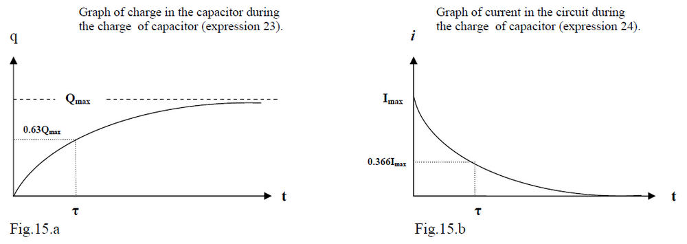
This charge function is shown in the Figure 15a.
Meaning of the time constant
At the charge in capacitor plates gets to
Thus, just looking at the time constant can give an idea of how fast or slow the circuit will charge the capacitor. The longer the time constant, the longer the circuit takes to charge the capacitor.
Current in a charging circuit
From the expression you can calculate the evolution of the current in the circuit.
As i = dq/dt you can just take the derivative of the charging function to find the current:
Initially, the charge rushes onto the capacitor, but as more charge accumulates, the current is reduced. The current will be maximum at t=0, and have a value of
Therefore:
This function is shown in figure 15.b.
DISCHARGING THE CAPACITOR
You discharge a capacitor by removing the battery and shorting out the two ends of the circuit. This is shown in the Figure 16:
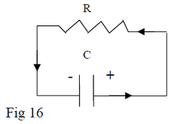
By using Kirchoff rule #2 for this circuit you get:
(25)
where is the potential across the capacitor terminals and
is the potential across the resistor.
You can rewrite eq.25 in the form
Substituting i = −dq / dt into this equation:
which can be transformed to
We take the integral of both sides
and get
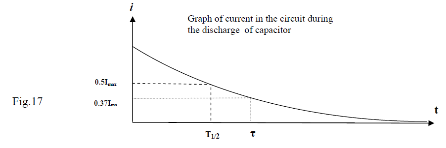
For t = τ we get q = Qmax / e = 0.37Qmax.
The “ half-time” noted as is the time it takes for the charge of the capacitor to get to half of its initial charge(q = 0.5Qmax);
so,
We finally get (28)
Current in a Discharging RC Circuit
Taking into account that during the discharge of a capacitor the current in the circuit is I = - dq/dt
Using the same notation as for the charging situation, that is ,
Note that this equation is the same as that for charging the capacitor!
Of course the current is opposite to the charging case, but the current function is the same.
Note that for we get and for :
The graph of the current in the circuit during
the discharge of capacitor is shown in Figure 17.
